Film-Tech Cinema Systems
Film-Tech Forum ARCHIVE


my profile | my password | search | faq & rules | forum home
  next oldest topic   next newest topic
» Film-Tech Forum ARCHIVE   » Operations   » Film Handlers' Forum   » Cinemeccanica Portacine Revisited (Page 1)

 
This topic comprises 2 pages: 1  2 
 
Author Topic: Cinemeccanica Portacine Revisited
Ian Partridge
Film Handler

Posts: 10
From: Colchester, Essex, England, United Kingdom
Registered: Mar 2016


 - posted 08-21-2016 04:52 AM      Profile for Ian Partridge   Author's Homepage   Email Ian Partridge   Send New Private Message       Edit/Delete Post 
This is a question about the feed guide roller directly above the gate on a Cinemeccanica 35mm.

 - Sprung roller flange pushed apart.

 - Roller flanges together

The hollow roller comprises of two parts with an internal expansion spring squeezing the two halves together. The film edges are supposed to run between the flanges, but in practice the film loop tends to be expelled slightly by the sprung flange? You can see that a circular groove has been worn previously on the flange bevel in the picture.

I noticed the front grub screw and cone bearing adjuster were tightened-up so that the front flange did not rotate, while the sprung back half could ?

I have adjusted the grub screw settings so that the roller is free to rotate as nature, and possibly Cinemeccanica, intended and also slightly adjusted the internal expansion spring to give less 'squeeze' to the film sides. But the upper loop still tends to dwell outside the flange sides at the bevel ?

Is it possible that the two halves have worn closer together because the cone bearings were locked ? In which case adding a shim washer to the middle would allow the film sides to be guided in the flanges as they should ?

Ian

 |  IP: Logged

Monte L Fullmer
Film God

Posts: 8367
From: Nampa, Idaho, USA
Registered: Nov 2004


 - posted 08-22-2016 02:59 AM      Profile for Monte L Fullmer   Email Monte L Fullmer   Send New Private Message       Edit/Delete Post 
More like the film path for the trap and gate assembly isn't fully straight-why the film wants to ride up on that one flange.

Please check all parameters in the film path first.

Good luck - Monte

 |  IP: Logged

Marco Giustini
Film God

Posts: 2713
From: Reading, UK
Registered: Nov 2007


 - posted 08-22-2016 07:38 AM      Profile for Marco Giustini   Email Marco Giustini   Send New Private Message       Edit/Delete Post 
There should be no or little play between the film and the 'fixed' flange, the one towards the bottom of the picture. Adjust both conical grub screws so that side is barely touching the film. Then - as you already did - adjust the other grub screw so the whole assembly is free to rotate, but with the minimum play possible.

The design of that thing is a joke so it may not be possible to prevent the film from jumping out of the path - particularly when a splice runs through - but it's worth a try.

 |  IP: Logged

Kenneth Wuepper
Phenomenal Film Handler

Posts: 1026
From: Saginaw, MI, USA
Registered: Feb 2002


 - posted 08-22-2016 09:34 AM      Profile for Kenneth Wuepper   Email Kenneth Wuepper   Send New Private Message       Edit/Delete Post 
The jumping from the "studio gate" can also be caused by an excessively large upper loop.

 |  IP: Logged

Mark Gulbrandsen
Resident Trollmaster

Posts: 16657
From: Music City
Registered: Jun 99


 - posted 08-22-2016 04:56 PM      Profile for Mark Gulbrandsen   Email Mark Gulbrandsen   Send New Private Message       Edit/Delete Post 
If you can acquire a piece of 35mm steel alignment film that would be best.

 |  IP: Logged

Ian Partridge
Film Handler

Posts: 10
From: Colchester, Essex, England, United Kingdom
Registered: Mar 2016


 - posted 08-23-2016 05:04 PM      Profile for Ian Partridge   Author's Homepage   Email Ian Partridge   Send New Private Message       Edit/Delete Post 
I have tried re-adjusting the roller according to the helpful suggestions given. And I appreciate all your knowlegeable forum advice.

I used two thicknesses of film stock which helped with first correcting alignment of the fixed flange of the roller. There is no adjustment for the sprung flange, but as directed, I tightened the grub screw to allow the cone bearing just enough to rotate freely.

On test, the upper loop is now very much improved, weaving in and out between the flanges. Before it was riding up even when inching. I may have left too much loop at the top (but followed the film path diagram) which allowed the loop to flex too much. It seems a mad design.

Ian

 |  IP: Logged

Monte L Fullmer
Film God

Posts: 8367
From: Nampa, Idaho, USA
Registered: Nov 2004


 - posted 08-23-2016 05:30 PM      Profile for Monte L Fullmer   Email Monte L Fullmer   Send New Private Message       Edit/Delete Post 
Ian, please take a look at this thread that I started back in 2006 on the threading

http://www.film-tech.com/cgi-bin/ubb/ultimatebb.cgi?ubb=get_topic;f=1;t=007823#000000

Maybe give this a try and see what happens.

Good luck - Monte

 |  IP: Logged

Nigel Shore
Film Handler

Posts: 2
From: Bournemouth. Dorset .UK
Registered: Jun 2006


 - posted 08-24-2016 10:09 AM      Profile for Nigel Shore   Email Nigel Shore   Send New Private Message       Edit/Delete Post 
Ian. You first take the roller apart. Be very careful not to lose the spring as you take the circlip off. Clean the bore on one half of the roller and the spindle on the other half. With smear of WD40 reassemble the roller. Make sure there is no crud in the point screw holes on both ends and make sure that the point screws are clean. Now the important bit. Refit the roller and using a straight edge (a 6" steel ruler or an aperture plate which is exactly 35mm wide) adjust the outer point screw so the film edge of the roller is exactly in line with the reference (soundtrack) edge of the gate plate. Adjust the opposite point screw so that the roller will rotate freely but with no end float. You will only need to just tighten the 2 grub screws, to hard and they will damage the point screw threads. DO NOT put a shim between the 2 halves of the roller. if it is fractionally too big you will get a dead centre emulsion scratch When running the film should sit into the roller which will only slightly turn. If it is badly grooved you'll need to replace it. Check that the top sprocket is hard against the shoulder on the shaft.
As for the statement that this roller is a joke I disagree. The same roller has been used on every V10/V8/V9/V4/V5, so for about 60 years If it springs freely and is adjusted correctly it works perfectly.

 |  IP: Logged

Leo Enticknap
Film God

Posts: 7474
From: Loma Linda, CA
Registered: Jul 2000


 - posted 08-27-2016 09:53 AM      Profile for Leo Enticknap   Author's Homepage   Email Leo Enticknap   Send New Private Message       Edit/Delete Post 
quote: Nigel Shore
Clean the bore on one half of the roller and the spindle on the other half.
I wonder if doing that would help the thin roller that always sticks just below the top entrance to the chassis on the Norelco AA/Philips DP70 mk. I? I have an ongoing battle with a pair that keep binding, and have to remove them and scrub the roller bore with a Q-tip (cotton bud) soaked in isopropanol, and apply a tiny coating of projector oil to the shaft, every couple of weeks to keep them rotating freely. It's a big film scratching risk if you don't keep a very close eye on it, which I suspect is why that roller was gotten rid of in the mk. II.

 |  IP: Logged

Dave Macaulay
Film God

Posts: 2321
From: Toronto, Canada
Registered: Apr 2001


 - posted 08-27-2016 07:35 PM      Profile for Dave Macaulay   Email Dave Macaulay   Send New Private Message       Edit/Delete Post 
WD40 is a very poor lubricant and will turn to gum quickly. Use sewing machine or clock oil, 3 in 1 electric motor oil if desperate. The intermittent oil is OK but a bit thick... use just a small amount.

 |  IP: Logged

Kenneth Wuepper
Phenomenal Film Handler

Posts: 1026
From: Saginaw, MI, USA
Registered: Feb 2002


 - posted 08-27-2016 07:40 PM      Profile for Kenneth Wuepper   Email Kenneth Wuepper   Send New Private Message       Edit/Delete Post 
There is a product called "Dry Slide". If you apply it with a small cotton tip and sparingly it will function very well and for a long time. It does not gum or flake as other products have in the past. It is also useful on the fire traps where lubrication to prevent scratches is very critical.

 |  IP: Logged

Ian Partridge
Film Handler

Posts: 10
From: Colchester, Essex, England, United Kingdom
Registered: Mar 2016


 - posted 08-28-2016 08:16 PM      Profile for Ian Partridge   Author's Homepage   Email Ian Partridge   Send New Private Message       Edit/Delete Post 
From the information given I decided that I should start again with the roller. On disassembling I noticed that the inner shaft bearing surface was dull and rough. Therefore the two halves did not spin freely as would be expected. The crevices of the flanges were also dull.

I used a small dab of the "fine" grade grey polishing powder from an old car valve grinding kit on a small square of tissue and simply rubbed away the roughness with forefinger and thumb, imparting a brightly polished finish to the roller halves of the shaft and shell and flanges. On the flange sides with the radial grooves worn by the film edges, I applied firm pressure with a thumb nail and these marks polished out qickly and easily in a couple of minutes. Then thoroughly rinsing the parts in isopropyl alcohol solvent before reassembly and a drop of light oil.
I used a printers' type scale (28mm wide)as a straight edge for alignment of the flanges. On a brief test with film the curve of the upper loop now dwells as it should between the roller flanges without riding up. So it appears that it was the unpolished roller dragging causing the film edges to jump out.

Which follows on to my further Portacine question concerning the framer adjustment? On the PC 35 diagram legend it shows the lower film path with the film fed between the two rollers at the lower loop? Since adjusting the framer in effect reduces or increases the size of the upper loop. In the position shown in the threading diagram the framer is shown pulled down to its fullest extent.

I would assume that the framer should be initially set exactly half and half way to allow for any necessary framer adjustment both up and down ?

Ian

 |  IP: Logged

Fredrik Sandstrom
Film Handler

Posts: 63
From: Turku, Varsinais-Suomi, FINLAND
Registered: Mar 2014


 - posted 08-29-2016 02:36 AM      Profile for Fredrik Sandstrom   Email Fredrik Sandstrom   Send New Private Message       Edit/Delete Post 
quote: Ian Partridge
I would assume that the framer should be initially set exactly half and half way to allow for any necessary framer adjustment both up and down ?
I prefer to set it in the extreme "up" position, to let the maximum number of intermittent teeth engage the film. Provided you thread in frame, and there are no incorrect splices in the film, this still gives you enough room for adjustments to fine-tune the framing. If I have reason to believe I will need to make bigger adjustments, I thread with the framer set one perf down. I don't like running in the extreme "down" position, as it seems to me the film is barely touching the intermittent sprocket then.

 |  IP: Logged

Ian Partridge
Film Handler

Posts: 10
From: Colchester, Essex, England, United Kingdom
Registered: Mar 2016


 - posted 08-29-2016 08:19 PM      Profile for Ian Partridge   Author's Homepage   Email Ian Partridge   Send New Private Message       Edit/Delete Post 
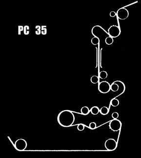
 - Cinemeccanica Portacine threading path diagram label.

Now I can understand why these are placed at 12 o'clock and not 9 o'clock.

I have noticed that there is also an inspection hole for inching up to align with a red dot when threading so that the frame dwells in correct position with the gate aperture.

Following the film path to just before the sound drum, there are three tension/guide rollers. The fat middle one is static, fixed, and does not rotate ? I assume this correct and is to create a slight 'drag'to keep the film tight and smooth around the sound drum ?

Ian

 |  IP: Logged

Fredrik Sandstrom
Film Handler

Posts: 63
From: Turku, Varsinais-Suomi, FINLAND
Registered: Mar 2014


 - posted 08-30-2016 02:19 AM      Profile for Fredrik Sandstrom   Email Fredrik Sandstrom   Send New Private Message       Edit/Delete Post 
quote: Ian Partridge
I have noticed that there is also an inspection hole for inching up to align with a red dot when threading so that the frame dwells in correct position with the gate aperture.
I think the purpose of the red dot is for timing the shutter with the intermittent (for example after replacing the drive belt), but sure, you can use it when threading too if you find it helpful.

quote: Ian Partridge
Following the film path to just before the sound drum, there are three tension/guide rollers. The fat middle one is static, fixed, and does not rotate ? I assume this correct and is to create a slight 'drag'to keep the film tight and smooth around the sound drum ?
Yes, that is correct, but unfortunately it does not work as well as it should. Many Portacine users (myself included) have noticed that especially polyester film will have flutter in playback. If you experience this problem, take a look at how I solved it: Portacine soundhead fix

My solution involves replacing one of the rollers with a sprocket, with an adjustable friction to provide suitable drag.

(Should my entire text be posted here for the forum archive? With or without images?)

 |  IP: Logged


All times are Central (GMT -6:00)
This topic comprises 2 pages: 1  2 
 
   Close Topic    Move Topic    Delete Topic    next oldest topic   next newest topic
 - Printer-friendly view of this topic
Hop To:


Powered by Infopop Corporation
UBB.classicTM 6.3.1.2

The Film-Tech Forums are designed for various members related to the cinema industry to express their opinions, viewpoints and testimonials on various products, services and events based upon speculation, personal knowledge and factual information through use, therefore all views represented here allow no liability upon the publishers of this web site and the owners of said views assume no liability for any ill will resulting from these postings. The posts made here are for educational as well as entertainment purposes and as such anyone viewing this portion of the website must accept these views as statements of the author of that opinion and agrees to release the authors from any and all liability.

© 1999-2020 Film-Tech Cinema Systems, LLC. All rights reserved.