Film-Tech Cinema Systems
Film-Tech Forum ARCHIVE


my profile | my password | search | faq & rules | forum home
  next oldest topic   next newest topic
» Film-Tech Forum ARCHIVE   » Operations   » Film Handlers' Forum   » Part ID needed on Strong Phase Controls (Page 1)

 
This topic comprises 2 pages: 1  2 
 
Author Topic: Part ID needed on Strong Phase Controls
Paul G. Thompson
The Weenie Man

Posts: 4718
From: Mount Vernon WA USA
Registered: Nov 2000


 - posted 09-03-2002 05:29 PM      Profile for Paul G. Thompson   Email Paul G. Thompson   Send New Private Message       Edit/Delete Post 

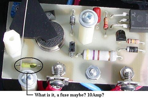
Does anyone have a schematic for these controls?

I have confirmed that the mystery device is indeed a 10 amp fuse.

The SCR is a NTE-5460.

The device under the light shutter and above the cadium cell is a LM-334, and crosses to nothing! What is it, and what is the substitute?

The device to the right and just under the SCR is a Silicone Unilateral Switch Thyristor Trigger. It crosses to a RCA SK7900.

Thanks for your inputs.


 |  IP: Logged

Sam Hunter
Jedi Master Film Handler

Posts: 779
From: West Monroe, LA, USA
Registered: Jan 2002


 - posted 09-03-2002 10:25 PM      Profile for Sam Hunter   Email Sam Hunter   Send New Private Message       Edit/Delete Post 
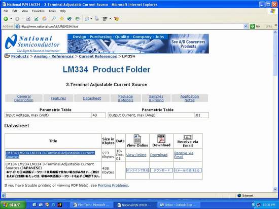
The LM334 is a 3 term adjustable regulator.
See below post for more info as I can't get the damn picture to load on this one.

------------------
Samual Hunter Sr.

KC5ZSL


 |  IP: Logged

Sam Hunter
Jedi Master Film Handler

Posts: 779
From: West Monroe, LA, USA
Registered: Jan 2002


 - posted 09-03-2002 10:37 PM      Profile for Sam Hunter   Email Sam Hunter   Send New Private Message       Edit/Delete Post 
Some info on LM334

The link http://www.national.com/pf/LM/LM334.html


------------------
Samual Hunter Sr.

KC5ZSL


 |  IP: Logged

Ken Layton
Phenomenal Film Handler

Posts: 1452
From: Olympia, Wash. USA
Registered: Sep 1999


 - posted 09-03-2002 10:41 PM
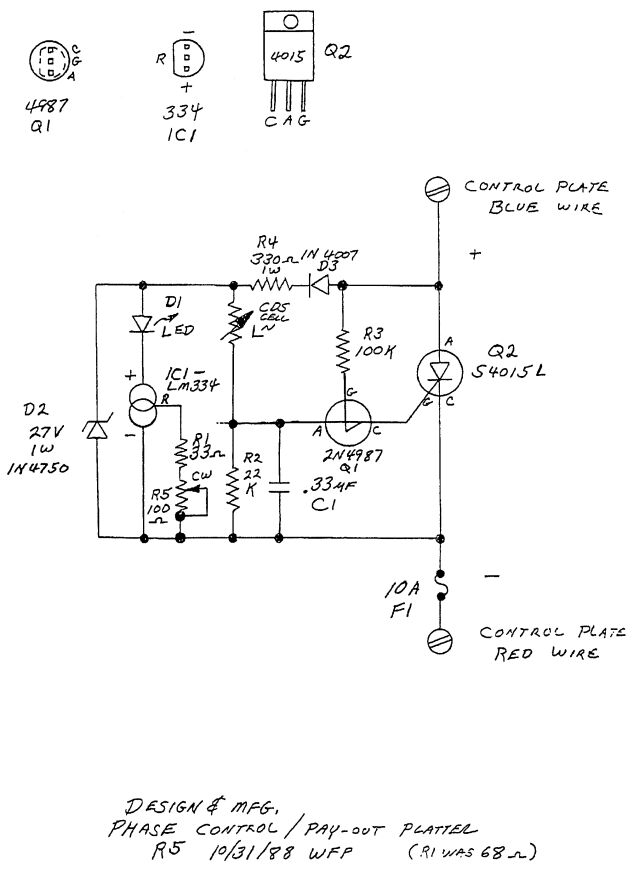
      Profile for Ken Layton   Email Ken Layton   Send New Private Message       Edit/Delete Post 
Paul:

The phase control repair info and schematic is already here on the manuals page under "Field Bulletins" -> "Strong Phase control adjustment and repair info".

The LM334z is a constant current source (Mouser number 511-LM334Z) and for the SCR, I use Mouser number 519-S6020L (isolated tab). As to your mystery component, it is a 10 amp pico fuse (Mouser number 5761-51010).


 |  IP: Logged

Ken Lackner
Phenomenal Film Handler

Posts: 1907
From: Atlanta, GA, USA
Registered: Sep 2001


 - posted 09-03-2002 10:48 PM      Profile for Ken Lackner   Email Ken Lackner   Send New Private Message       Edit/Delete Post 
Ken: Correct me if I'm wrong, but if everything else on that schematic is correct it looks as if the 1N4004 diode on the schematic is reverse biased. Are the supply terminals by any chance misslabeled? Am I missing something?


 |  IP: Logged

Ken Layton
Phenomenal Film Handler

Posts: 1452
From: Olympia, Wash. USA
Registered: Sep 1999


 - posted 09-03-2002 11:00 PM      Profile for Ken Layton   Email Ken Layton   Send New Private Message       Edit/Delete Post 
It's possible the supply terminals are mislabeled since I drew that schematic by hand. Design & Mfg would not release any schematics, grrr. So I had to reverse engineer it.

 |  IP: Logged

Ken Lackner
Phenomenal Film Handler

Posts: 1907
From: Atlanta, GA, USA
Registered: Sep 2001


 - posted 09-03-2002 11:17 PM      Profile for Ken Lackner   Email Ken Lackner   Send New Private Message       Edit/Delete Post 
Actually, going by the Phase Control Instilation field bulletin, which tells you where the red and blue wires go, and Paul's picture above, it looks like your schematic is correct. I just don't get why the diode is facing the way it is. Unless Blue is positive??? I must be missing something.

 |  IP: Logged

Sam Hunter
Jedi Master Film Handler

Posts: 779
From: West Monroe, LA, USA
Registered: Jan 2002


 - posted 09-03-2002 11:36 PM      Profile for Sam Hunter   Email Sam Hunter   Send New Private Message       Edit/Delete Post 
I think the polarity is mismarked on the terminals.
Also look closely at the photo below and you can see that the diodes anode does indeed connect to the terminal which means the diode polarity on the Schematic is correct.

------------------
Samual Hunter Sr.

KC5ZSL

 |  IP: Logged

Paul G. Thompson
The Weenie Man

Posts: 4718
From: Mount Vernon WA USA
Registered: Nov 2000


 - posted 09-03-2002 11:46 PM      Profile for Paul G. Thompson   Email Paul G. Thompson   Send New Private Message       Edit/Delete Post 
Both Kens....

I downloaded the schematic. 1N4004 does appear to be reversed biased, but I think that is the way it is supposed to be. It looks like basically it is in series with the LED and the LM334Z, which would serve as a rectified AC source for the 3-volt LED. Maybe the Zener is used to prevent inductive spikes from the motor from trashing the SCR. (just a guess)

Anyway, I put in a new NTE SCR and a fuse. Apparently they were destroyed when the wire fell off the pin plug while it was in the spindle and shorted to ground.

Installed the newly repaired Phase Control on a CFS Super Platter, and I was very pleased with the results. I observed an average of a slow 90 degree oscillation of the pay-out, which was far superior to the 360 degree over-shoot and a 360 degree under-shoot I have been seeing with Micro-Switches. Because of the 10 Ohm 25-Watt resistor that shunts the entire shebang on pay-out, It made the Strong A-3 look like a POS!

(Sorry, Pat....but tell your platter guys to put that resistor in place. They don't use it in the A-3. That is one of the reason for major over-shoots and under-shoots of the A-3 when they are converted to Micros. The motor is either OFF or ON! With the 10 Ohm 25-Watt resistor in place, it is a "Soft Off" for a slow run-down, and then a "Soft ON" for a slow ramp-up.) The results? No whipping of the platter, and no tossing of prints. Ask your platter engineers to make improvements - they are needed to stay competitive with folks from Christie, SPECO and Kineton.

Now you know why a CFS micro-switch platter out-performs an A3 with micro-switches. This should breath new life in the old Super Platters some of you guys hate so much. Between the two, I would prefer a 20 year-old Super Platter with Phase Controls over a Strong/Potts A3 with Micro switches. The proof is clear from my observations this evening. (I particularly liked the "Ooooo's and Ahhhhhh's" from the operators when they seen the results of the Phase Control.)

Sam, I was eyeballing that junction as you have shown. I think Ken was using "Instant Polarities" that apparently throws confusion into the works. However, Ken's schematic is correct.


 |  IP: Logged

Ken Layton
Phenomenal Film Handler

Posts: 1452
From: Olympia, Wash. USA
Registered: Sep 1999


 - posted 09-03-2002 11:59 PM      Profile for Ken Layton   Email Ken Layton   Send New Private Message       Edit/Delete Post 
I also convert the "R2" version of the phase control into the "R3" version for the best reliability. I keep a stock of spare components to repair the phase control units. If you get a chance Paul, how about posting a picture of the Phase Control installed on a Super Platter?

 |  IP: Logged

Paul G. Thompson
The Weenie Man

Posts: 4718
From: Mount Vernon WA USA
Registered: Nov 2000


 - posted 09-04-2002 12:05 AM      Profile for Paul G. Thompson   Email Paul G. Thompson   Send New Private Message       Edit/Delete Post 
Ken, it is the retro-fit brain supplied by Brownfield for the CFS platter. It is identical to the brain that is on the A-3, except for the plug-in base. As much as I would like to convert the CFS platters to removable pay-out heads, I probably will not. The retrofit kits for the spindles are complete .

Here is your request:

Damn...How did Poopers (my Beagle) manage to get one of his hairs by the angle roller? Poops done right. He sniffed it and gave it his approval. At least, his "deposite" was not something else that is usually accompanied with a SNORT!


 |  IP: Logged

Rick Sanjurjo
Film Handler

Posts: 26
From: Omaha, NE, USA
Registered: Jul 2002


 - posted 09-06-2002 05:22 PM      Profile for Rick Sanjurjo   Email Rick Sanjurjo   Send New Private Message       Edit/Delete Post 
The SCR is S4015L
The switch is 2N4987
The fuse is a 10A pico fuse

I will post a schematic on Monday when I can scan it in.

Rick

 |  IP: Logged

Paul G. Thompson
The Weenie Man

Posts: 4718
From: Mount Vernon WA USA
Registered: Nov 2000


 - posted 09-06-2002 09:38 PM      Profile for Paul G. Thompson   Email Paul G. Thompson   Send New Private Message       Edit/Delete Post 
Thanks, Rick. The proper set-up with the trim pot will help, too. I set mine to where the platter will stall on the pay-out mode with the swing arm to full off when the elevator is pinned in the threading hole. I don't know if that is correct or not, but that is what I did when I put it on the CFS platter. It seems to work fine.

On start-up the elevator does its normal wild things, but when it finds its null within the first 10 seconds or so, it runs like a champ.

Please - don't anyone else make that adjustment on the trim pot until Rick answers. There might be a better way.


 |  IP: Logged

Paul G. Thompson
The Weenie Man

Posts: 4718
From: Mount Vernon WA USA
Registered: Nov 2000


 - posted 09-10-2002 01:18 AM      Profile for Paul G. Thompson   Email Paul G. Thompson   Send New Private Message       Edit/Delete Post 
Hey Rick....we are waiting for your schematic..

 |  IP: Logged

Rick Sanjurjo
Film Handler

Posts: 26
From: Omaha, NE, USA
Registered: Jul 2002


 - posted 09-10-2002 01:43 PM      Profile for Rick Sanjurjo   Email Rick Sanjurjo   Send New Private Message       Edit/Delete Post 

Hope this helps

Rick

 |  IP: Logged


All times are Central (GMT -6:00)
This topic comprises 2 pages: 1  2 
 
   Close Topic    Move Topic    Delete Topic    next oldest topic   next newest topic
 - Printer-friendly view of this topic
Hop To:


Powered by Infopop Corporation
UBB.classicTM 6.3.1.2

The Film-Tech Forums are designed for various members related to the cinema industry to express their opinions, viewpoints and testimonials on various products, services and events based upon speculation, personal knowledge and factual information through use, therefore all views represented here allow no liability upon the publishers of this web site and the owners of said views assume no liability for any ill will resulting from these postings. The posts made here are for educational as well as entertainment purposes and as such anyone viewing this portion of the website must accept these views as statements of the author of that opinion and agrees to release the authors from any and all liability.

© 1999-2020 Film-Tech Cinema Systems, LLC. All rights reserved.