
Modifying a Simplex 5 Star Soundhead to be More Film Friendly
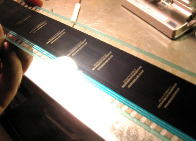 This is a trailer that was run for less than a week through a factory-set Simplex 5 Star soundhead. Notice the nasty streak it leaves, and it gets worse the longer you run fim through it. You can always tell if a film has run through a Simplex projector simply by looking at it. This is a modification to remove that obnoxious part and replace it with a spacer which does not touch the film. Required parts and tools: -9/64 Allen/hex wrench -5/64 Allen/hex wrench -Slotted screwdrivers, one to two medium size and one small -A 5/8 long spacer with a 1/4 inch inner diameter. They can be ordered HERE as of this writing, part number AS50-14-40, 70 cents each. -Buzz track test film -Dolby Tone test film -A fine repertoire of curse words. 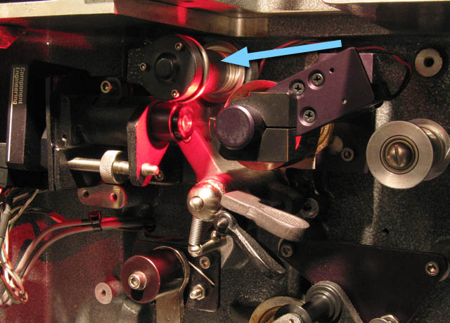 Here it is, the Simplex 5 Star soundhead. Just look at it. It's so stupid. The arrow points to the part we will replace. If you haven't figured it out by now, this mod will only work on the 5 Star soundhead, not the SH1000 or whatnot. Let's begin. 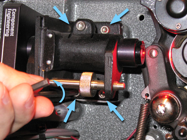 Begin by removing the screws which keep the sound lens assembly in place with your 9/64 hex wrench. If you have an older unit, you will need a slotted screwdriver for this task. Loosen, but do not remove the screw in the upper left corner. Remove the other three screws and don't lose them. 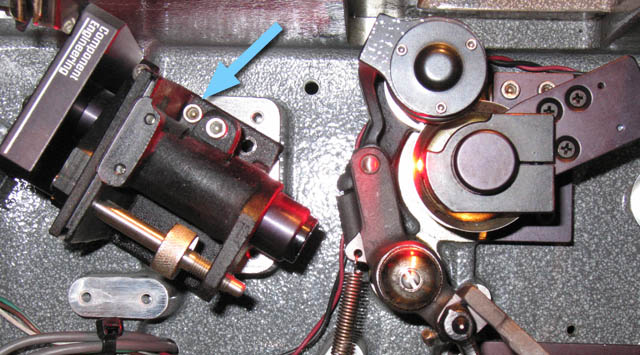 Pivot the sound lens assembly out of the way and then tighten the upper left screw so it stays in place as pictured. 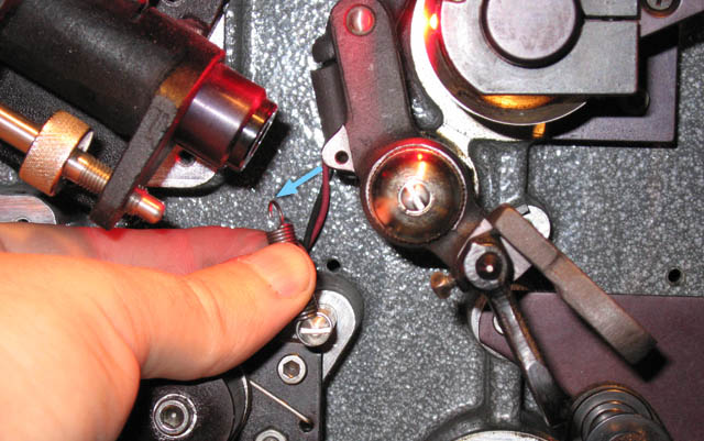 Gently remove the spring from the lateral guide assembly. 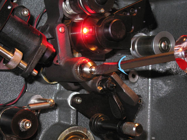 Loosen but do not remove the locking pin for the lateral adjustment "stop nut". 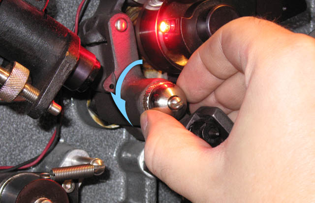 Remove the lateral adjustment "stop nut" and place it near the other screws you removed. 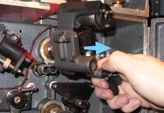 Carefully pull out the entire lateral guide roller assembly. Be sure the spring and anything else stays on the shaft you just removed it from. 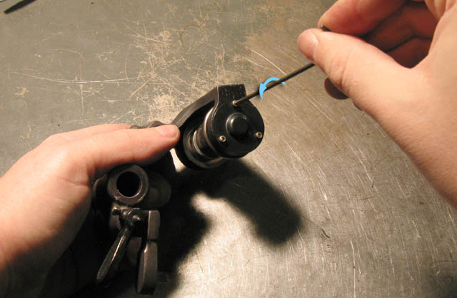 Bring the assembly over to a well-lit workbench or maybe outside in the sun if lights are forbidden in your booth. Use the 5/64 hex wrench to remove the three screws from the cap. If you have an older unit, you will need to use the small slotted screwdriver for this purpose. 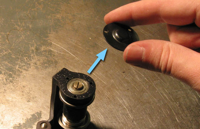 Remove the cap and place it somewhere where it will be happy and not in danger. 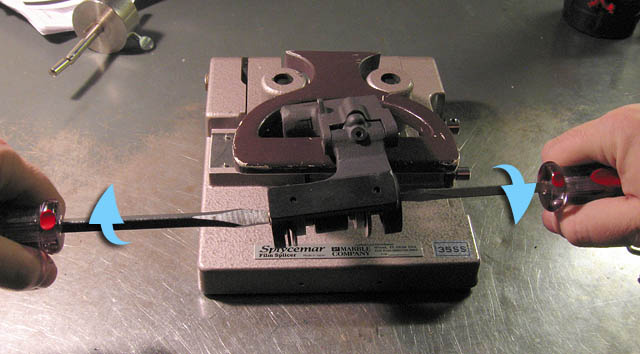 Now you'll need to loosen one of the two slotted screws which is easier said than done since they both make each other spin. If your booth has a vice grip, use that. Otherwise I find that a splicer handle works great for keeping the assembly in place while you use two hands to loosen the screws. If you have 3 hands, you will not need a vice or a splicer handle. 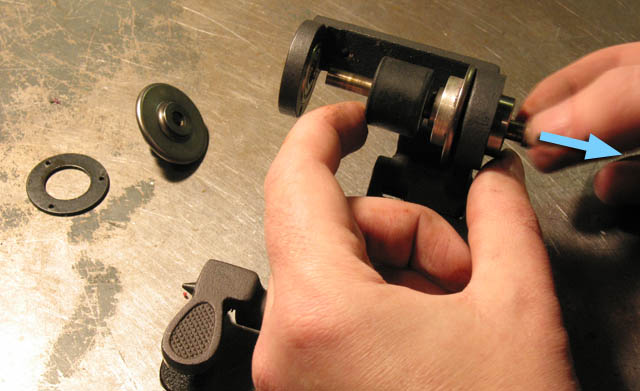 Once you have one of the screws removed (preferably the one from the side which had the cap you just removed), poke the shaft so it slides out the other way as shown. If you do it this way, you won't have to worry about dropping the spring or its washer. Remove the spacer plate and the outboard roller and set them aside. 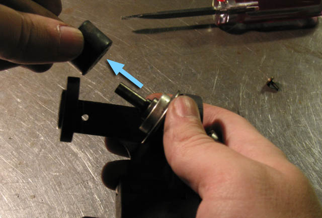 Remove this piece of crap. 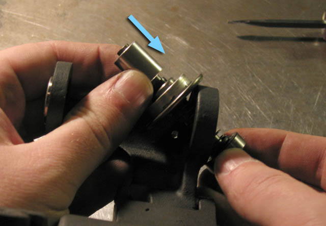 Slide the aluminum spacer on in its place. 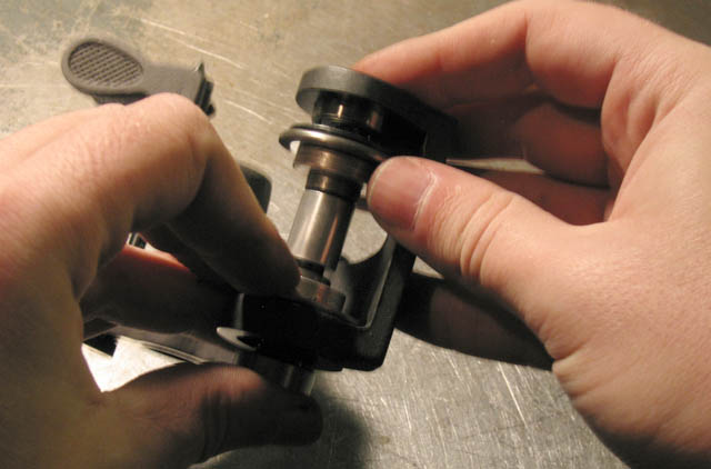 Put the outboard roller and spacer plate back on in the order you removed them. Make sure the bearing stays put. Slide the shaft back through everything. 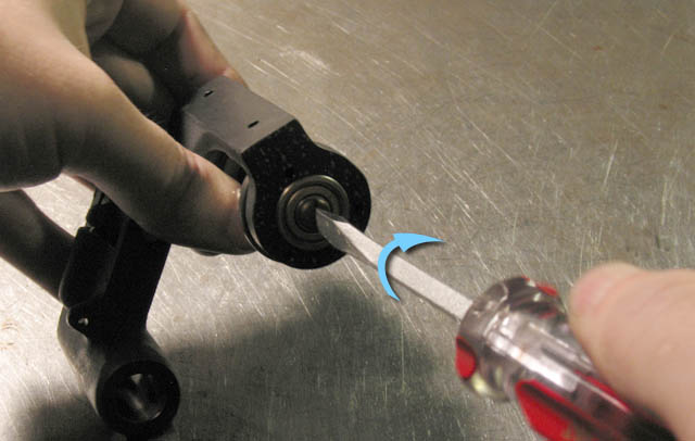 Put the slotted screw back on and make sure it is snug. You may need to use the splicer method again to make sure that it is snug enough and will not come loose on its own. 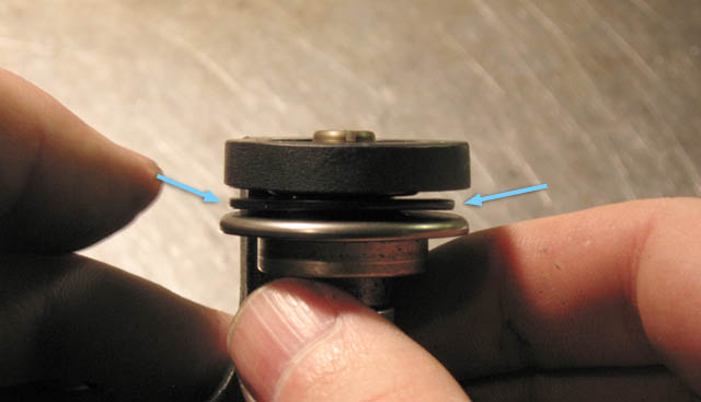 See that? That's the spacer plate. This needs to be reattached to the cap you removed with three screws. This is where you will use the curse words you gathered before you began this project. 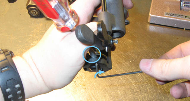 I don't have too many good tips for this other than to use a slotted screwdriver to press the plate up (after you align the holes) as you screw the cap back on from the other side. The cap may appear to be simply cosmetic since there isn't one for the other side, but it does help the bearing from sliding outward so it is a good idea to put it back on. Good luck. And they call this thing a Simplex? More like Diffiplex. Am I right? 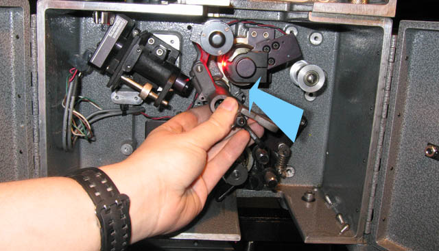 Now slide the entire assembly back onto the shaft. 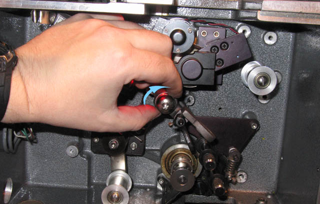 Put the lateral guide adjustment "stop nut" back on. Do not tighten it all the way, of course, but a few turns from where it stops is good. Do not tighten the locking pin in its center as you still need to run buzz track. 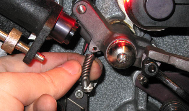 Kindly reattach the spring. 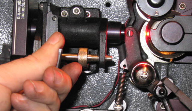 Move the sound lens assembly back into place and reinsert and tighten screws. 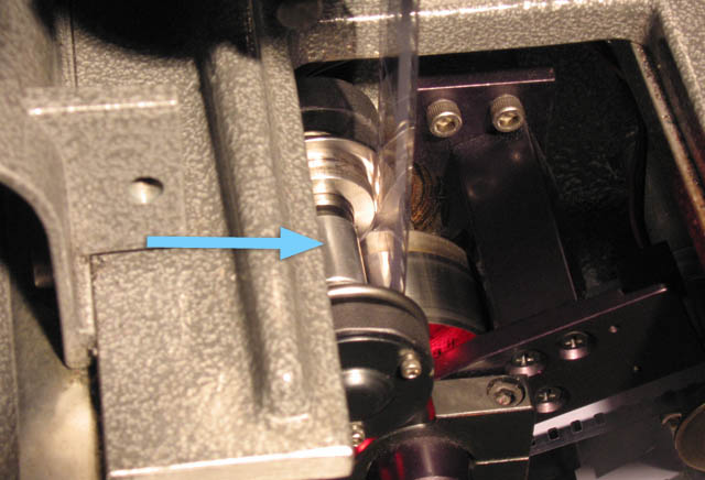 And here is our new part which is NOT touching the film in any way. Now nobody who gets prints after you will not be able to tell that you have Simplex projectors, saving you much embarrassment. Now, at minimum, run your buzz track and tone loops. But you might as well use this as an excuse to do a full A-chain. Now that you have replaced all of the crappy "friction rollers" in your entire theater complex, what do you do with them? Here are some ideas to help make them useful: 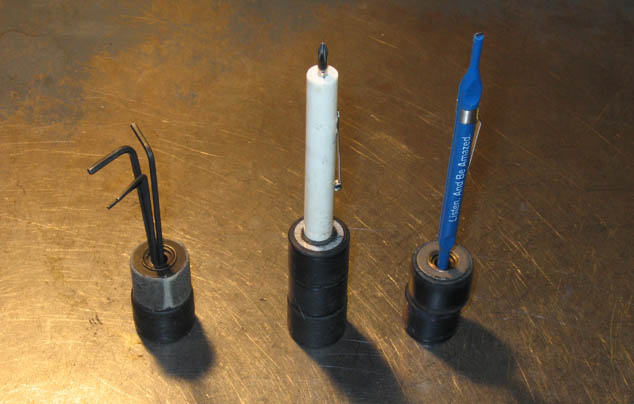 Storage for small tools. 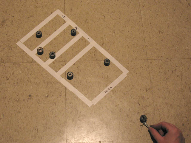 Mini Shuffleboard. 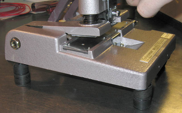 Stilts for your splicer in case your booth is prone to high waters. 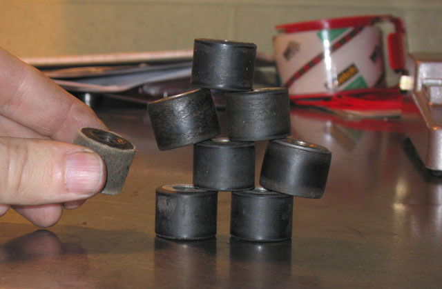 And who can forget Mini Jenga? NOTE: Perform this modification at your own risk. If it does not work for you and/or you mess something up, it is not the liability of the author or of Film-Tech. Please note that this has not yet been tested on basement Dolby Digital readers. |
..
by Joe Redifer
..